DESCRIPCION
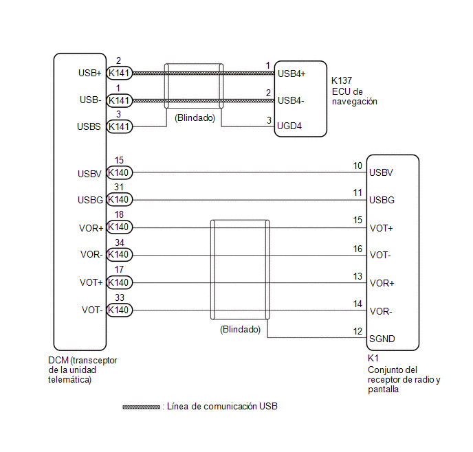
Este circuito se utiliza para enviar y recibir senales entre el DCM (Transceptor de Telematica) y el conjunto del receptor de radio y pantalla o la ECU de navegacion.
DIAGRAMA DE CONEXIONES

PROCEDIMIENTO
| 1. |
INSPECCIONE EL MAZO DE CABLES Y EL CONECTOR (CONJUNTO DE RECEPTOR DE RADIO Y PANTALLA - DCM (TRANSCEPTOR DE TELEMATICA)) |
(a) Desconecte el conector K140 del DCM (Transceptor de Telematica).
(b) Desconecte el conector K1 del conjunto del receptor de radio y pantalla.
(c) Mida la resistencia segun los valores de la siguiente tabla.
Resistencia estandar:
|
Conexion del tester | Condicion |
Condicion Especificada |
|---|---|---|
|
K140-31 (USBG) - K1-11 (USBG) |
Siempre | Inferior a 1 ? |
|
K140-17 (VOT+) - K1-13 (VOR+) |
Siempre | Inferior a 1 ? |
|
K140-15 (USBV) - K1-10 (USBV) |
Siempre | Inferior a 1 ? |
|
K140-33 (VOT-) - K1-14 (VOR-) |
Siempre | Inferior a 1 ? |
|
K140-34 (VOR-) - K1-16 (VOT-) |
Siempre | Inferior a 1 ? |
|
K140-18 (VOR+) - K1-15 (VOT+) |
Siempre | Inferior a 1 ? |
|
K140-31 (USBG) o K1-11 (USBG) - Masa de la carroceria |
Siempre | 10 k? o superior |
|
K140-17 (VOT+) or K1-13 (VOR+) - Masa de la carroceria |
Siempre | 10 k? o superior |
|
K140-15 (USBV) o K1-10 (USBV) - Masa de la carroceria |
Siempre | 10 k? o superior |
|
K140-33 (VOT-) o K1-14 (VOR-) - Masa de la carroceria |
Siempre | 10 k? o superior |
|
K140-34 (VOR-) o K1-16 (VOT-) - Masa de la carroceria |
Siempre | 10 k? o superior |
|
K140-18 (VOR+) or K1-15 (VOT+) - Masa de la carroceria |
Siempre | 10 k? o superior |
| NG | .gif) | REPARE O SUSTITUYA EL MAZO DE CABLES O EL CONECTOR |
|
| 2. |
INSPECCIONE EL MAZO DE CABLES Y EL CONECTOR (ECU DE NAVEGACION - DCM - TRANSCEPTOR DE LA UNIDAD TELEMATICA) |
| (a) Desconecte el conector K141 del DCM (transceptor de la unidad telematica). |
|
(b) Desconecte el conector K137 de la ECU de navegacion.
(c) Mida la resistencia segun los valores de la siguiente tabla.
Resistencia estandar:
|
Conexion del tester | Condicion |
Condicion Especificada |
|---|---|---|
|
K141-1 (USB-) - K137-2 (USB4-) |
Siempre | Inferior a 1 ? |
|
K141-2 (USB+) - K137-1 (USB4+) |
Siempre | Inferior a 1 ? |
|
K141-3 (USBS) - K137-3(UGD4) |
Siempre | Inferior a 1 ? |
|
K141-1 (USB-) o K137-2 (USB4-) - Masa de la carroceria |
Siempre | 10 k? o superior |
|
K141-2 (USB+) or K137-1 (USB4+) - Masa de la carroceria |
Siempre | 10 k? o superior |
|
K141-3 (USBS) o K137-3 (UGD4) - Masa de la carroceria |
Siempre | 10 k? o superior |
| OK | .gif) | CONTINUE CON LA SIGUIENTE AREA POSIBLEMENTE AFECTADA, TAL COMO SE MUESTRA EN LA TABLA DE SINTOMAS DE PROBLEMAS |
| NG | .gif) | REPARE O SUSTITUYA EL MAZO DE CABLES O EL CONECTOR |
 No reconoce los comandos de voz ejecutados para comunicarse con el centro de asistencia
Cortocircuito a masa o circuito abierto en el circuito de tensión de alimentación del sensor de velocidad de la rueda delantera derecha (C14E314)
DESCRIPCIÓN Consulte el DTC C050612 Haga clic aquí
No. de DTC Detection Item
Condición de detección de DTC
Área Afectada C14E314
Cortocircuito a masa o circuito abierto en el circuito de tensión de alimentación del sensor de velocidad de la rueda delantera dere ...
Componentes
COMPONENTES ILUSTRACION
*1 SENSOR DE PRESION DEL COMBUSTIBLE
*2 SOPORTE DEL SENSOR DE PRESION DEL COMBUSTIBLE NO. 1
Par de apriete para "Zonas principales que implican el rendimiento basico del vehiculo, como moverse/girar/detenerse": N*m (kgf*cm, lbf*pi.)
? ...
Montaje
MONTAJE PRECAUCIÓN / AVISO / OBSERVACIÓN
OBSERVACIÓN:
Lleve a cabo el mismo procedimiento para los lados izquierdo y derecho.
El procedimiento que se indica a continuación es para el lado izquierdo.
PROCEDIMIENTO 1. COLOQUE EL CONJUNTO DE LOS INTERMITENTES LATERALES (con intermit ...